The purpose of this lab was to introduce us to the use of breadboards and DMMs in basic electrical circuits. We were also introduced to the concept of electrical resistance.
PROCEDURE:
As illustrated in the ENGR 44 Lab book, connect the leads of the DMM to two holes with:
- the same column on one side of the channel.
- the same column on opposite sides of the channel.
- different columns on opposite sides of the channel.
- same as #3, but with a jumper wire connecting the two columns.
ANALYSIS:
Case 1:
R = 0.5 ohms

Case 2:
R = infinity ohms

Case 3:
R = infinity ohms

Case #4:
R = 0.6 ohms

CONCLUSION:
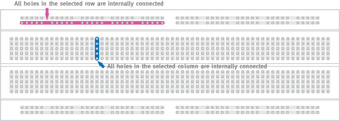
In case 1, we measured a resistance of 0.5 ohms between two holes on the same side of the channel, we can conclude that it is a closed circuit. For case 2, we measured infinity ohms between two holes on the same column on opposite sides of the channel, there is no continuity between them. Thus, we can infer that it is an open circuit. Similarly, in the third case, we measured infinity ohms between two holes on different columns on opposite sides of the channel. This indicates that we have an open circuit with this setup. However, if we modify this set up such that there is a jumper cable connecting the two columns, then we measure a resistance of 0.6 ohms. This demonstrates that we have created a closed circuit between these two holes. Using this information, we can infer that electrical connections across the channel are open unless they are connected using a jumper wire. Furthermore, we can conclude that holes connected by the same column on one side of the channel are closed circuits. I think the following image provides a concise representation of the internal connections of this breadboard:
For more info, click here.